
The differences between various types of the AT29C256 (a 256Kbit [32K x 8] 5-volt only Flash memory chip) primarily relate to speed, packaging, temperature ratings, and manufacturing reliability. While the core memory functionality remains the same, these factors determine the best fit for specific applications.
Here are the key areas of variation based on part number suffixes:
1. Access Speed (Speed Ratings)
The numbers following the hyphen (e.g., 90, 12, 15) indicate the maximum access time in nanoseconds (ns).
2. Package Types
The package affects how the chip is soldered or socketed onto a board.
3. Temperature Range and Reliability
Suffixes after the package type indicate the environmental rating.
4. Part Number Breakdown Example (AT29C256-90TI)
Trellis AI: https://trellis3d.co/
Anything World: https://app.anything.world/
ElevenLabs: https://elevenlabs.io/
Typecast: https://typecast.ai/
Suno: https://suno.com/
Soundraw: https://soundraw.io/
Passthrough relighting (for mixed reality)
This video explains how to use passthrough relighting in Quest 3 with Unity:
Mixed reality (MR) passthrough lighting
Quest 3 passthrough applications must solve the complex problem of blending virtual and real-world lighting. This requires using the Meta SDK to create virtual lights and shadows that interact with your actual physical environment.
1. Enable passthrough relighting
Passthrough Support to Supported.2. Configure shadows and occlusion
3. Estimate real-world lighting for reflections
To make virtual objects reflect real-world light, you can leverage the headset’s cameras to generate a real-time reflection probe.
Realtime Lighting Estimation on Quest 3
This video demonstrates the unlocked potential of Meta Quest 3 Camera Access via the Media Projection API. When mapped to a cubemap and projected onto a real-time reflection probe in Unity, you can finally use the environment to light your PBR materials. This dramatically improves the plausibility of the 3D Model in the environment – especially of course when you are in Mixed Reality. The video shows how this approach allows to adopt to different lighting conditions in “Real Time”.
For Meta Quest 3 and Unity, use mixed lighting with a combination of baked lighting for static objects and real-time lighting for dynamic objects to balance performance and visual quality. Key optimization techniques include using the Lightmap parameter for baked lighting, leveraging light probes for dynamic objects, and for passthrough AR, using the passthrough relighting features for realistic blending with the real world.
This video explains the basics of lighting in Unity, including real-time, baked, and mixed lighting:
Lighting types and performance
Key considerations for Quest 3 lighting link1, link2
Optimization and setup
You can watch this video to learn how to optimize lighting in Unity for VR on Quest:
Window > Rendering > Lighting to open the Lighting window.Optimizations for Quest 3
Window > Rendering > Lighting in the Unity editor. You can adjust scene lighting and optimize your precomputed lighting data here. This video explains how to use light probes to optimize lighting in VR:
Optimizing Universal Render Pipeline (URP) shadow settings for the Quest 3 requires balancing visual fidelity with performance. The goal is to achieve realistic-looking shadows that don’t cause frame rate drops, which are particularly jarring and disorienting in VR.
Most shadow settings are found in your URP Asset, which you can locate in your project’s Assets > Settings folder. The settings should be configured differently for your directional “main light” versus additional lights like spots and points.
Shadow performance fundamentals
Before adjusting settings, remember these key concepts:
URP Asset shadow settings
Access your URP Asset and navigate to the Shadows section to adjust these settings:
Main light shadows
The settings for your directional light are crucial, as it typically illuminates the largest area.
Additional lights (point and spot)
Optimizing shadow casters
In addition to the global URP settings, you can optimize shadows on a per-object basis.
Mesh Renderer component and set Cast Shadows to Off for non-essential items.Mesh Renderer, set Cast Shadows to Off. On the simplified mesh, set Cast Shadows to Shadows Only.Mesh Renderer components.Shadow artifacts and profiling
Other ways to optimize shadows in Unity for VR
Beyond scripts and URP settings, several other techniques can dramatically optimize shadows for VR, especially on mobile VR devices like the Quest 3. These methods often trade a small amount of visual quality for a significant gain in performance.
1. The Shadowmask lighting mode
This is a hybrid approach that provides high-quality static shadows while also allowing for real-time shadows from dynamic objects.
Project Settings > Quality and set the Shadowmask Mode to Shadowmask.Contribute Global Illumination enabled and Cast Shadows set to On.Window > Rendering > Lighting). 2. Simplified shadow meshes
For complex or high-poly models, rendering the full mesh into the shadow map is computationally expensive. Using a low-poly proxy mesh for shadow casting can save significant GPU time.
Mesh Renderer, set Cast Shadows to Off.Shadows Only. 3. Blob shadows
For less realistic art styles, blob shadows are a classic performance optimization trick. Instead of rendering a complex shadow map, you project a simple, circular, or custom-textured decal onto the ground below a character.
4. Occlusion culling
While not a shadow-specific technique, occlusion culling can indirectly boost shadow performance by reducing the number of objects rendered.
Window > Rendering > Occlusion Culling window, bake the occlusion data.5. Level of Detail (LOD) for shadows
For objects with LOD groups, you can configure their lower-detail levels to not cast shadows or to use a simplified shadow.
Mesh Renderer on that LOD level to disable shadow casting. This saves rendering time for shadows that would be imperceptible at a distance.Mesh Renderer component for the farther LOD levels, set the Cast Shadows property to Off. Examples of scripts that disable shadows based on distance
For VR development, you should generally rely on the URP Shadow Distance setting to manage shadow visibility based on distance for all objects. For more specific needs, like disabling shadows for a single moving object that is far away, you can use scripts.
1. Script for a single dynamic object
This script is attached to a specific GameObject to manage its shadow-casting behavior. The script compares the object’s distance from the main camera to a predefined threshold.
using UnityEngine;

[RequireComponent(typeof(MeshRenderer))]
public class DistanceBasedShadows : MonoBehaviour
{
    // The main camera in the scene. In VR, this is the camera that renders the player's view.
    private Transform mainCameraTransform;

    // The MeshRenderer component of this object.
    private MeshRenderer meshRenderer;

    // The maximum distance at which the object should cast shadows.
    public float maxShadowDistance = 20f;

    // A small buffer distance to prevent constant flickering at the threshold.
    public float distanceHysteresis = 2f;

    // The initial shadow casting mode.
    private UnityEngine.Rendering.ShadowCastingMode initialShadowCastingMode;

    void Start()
    {
        // Find the main camera.
        mainCameraTransform = Camera.main.transform;

        // Get the MeshRenderer component.
        meshRenderer = GetComponent<MeshRenderer>();

        // Store the initial shadow casting mode to restore later.
        initialShadowCastingMode = meshRenderer.shadowCastingMode;
    }

    void Update()
    {
        // If the main camera is not set, exit to prevent errors.
        if (mainCameraTransform == null)
        {
            return;
        }

        // Calculate the distance from the camera to this object.
        float distance = Vector3.Distance(transform.position, mainCameraTransform.position);

        // Toggle shadows based on the distance.
        if (distance > maxShadowDistance)
        {
            // Disable shadows if they are not already off.
            if (meshRenderer.shadowCastingMode != UnityEngine.Rendering.ShadowCastingMode.Off)
            {
                meshRenderer.shadowCastingMode = UnityEngine.Rendering.ShadowCastingMode.Off;
            }
        }
        else if (distance < maxShadowDistance - distanceHysteresis)
        {
            // Re-enable shadows if they are not already on and the object is close enough.
            if (meshRenderer.shadowCastingMode != initialShadowCastingMode)
            {
                meshRenderer.shadowCastingMode = initialShadowCastingMode;
            }
        }
    }
}
2. Script for managing multiple objects
For a cleaner approach, you can create a single “manager” script that controls multiple shadow-casting objects. This avoids the overhead of having an Update loop running on many individual game objects.
using System.Collections.Generic;
using UnityEngine;

public class ShadowDistanceManager : MonoBehaviour
{
    // A list of all the MeshRenderers that this script will manage.
    public List<MeshRenderer> managedRenderers;

    // The main camera in the scene.
    private Transform mainCameraTransform;

    // The maximum distance for shadows.
    public float maxShadowDistance = 20f;

    // A small buffer to prevent flickering at the threshold.
    public float distanceHysteresis = 2f;

    // Storage for the initial shadow casting mode of each renderer.
    private Dictionary<MeshRenderer, UnityEngine.Rendering.ShadowCastingMode> initialModes = new Dictionary<MeshRenderer, UnityEngine.Rendering.ShadowCastingMode>();

    void Start()
    {
        mainCameraTransform = Camera.main.transform;

        // Store the initial state of each renderer.
        foreach (var renderer in managedRenderers)
        {
            if (renderer != null)
            {
                initialModes[renderer] = renderer.shadowCastingMode;
            }
        }
    }

    void Update()
    {
        if (mainCameraTransform == null)
        {
            return;
        }

        // Iterate through all managed renderers.
        foreach (var renderer in managedRenderers)
        {
            if (renderer == null) continue;

            float distance = Vector3.Distance(renderer.transform.position, mainCameraTransform.position);

            // Toggle shadows based on distance.
            if (distance > maxShadowDistance)
            {
                if (renderer.shadowCastingMode != UnityEngine.Rendering.ShadowCastingMode.Off)
                {
                    renderer.shadowCastingMode = UnityEngine.Rendering.ShadowCastingMode.Off;
                }
            }
            else if (distance < maxShadowDistance - distanceHysteresis)
            {
                if (renderer.shadowCastingMode != initialModes[renderer])
                {
                    renderer.shadowCastingMode = initialModes[renderer];
                }
            }
        }
    }
}
3. Script for a single point or spot light
This script manages the shadows of a specific light source, such as a torch or lamp, disabling them when the light is far from the player.
using UnityEngine;

[RequireComponent(typeof(Light))]
public class LightShadowToggler : MonoBehaviour
{
    private Transform mainCameraTransform;
    private Light lightComponent;

    public float maxShadowDistance = 15f;
    public float distanceHysteresis = 1f;

    private LightShadows initialShadowsSetting;

    void Start()
    {
        mainCameraTransform = Camera.main.transform;
        lightComponent = GetComponent<Light>();
        initialShadowsSetting = lightComponent.shadows;
    }

    void Update()
    {
        if (mainCameraTransform == null)
        {
            return;
        }

        float distance = Vector3.Distance(transform.position, mainCameraTransform.position);

        if (distance > maxShadowDistance)
        {
            if (lightComponent.shadows != LightShadows.None)
            {
                lightComponent.shadows = LightShadows.None;
            }
        }
        else if (distance < maxShadowDistance - distanceHysteresis)
        {
            if (lightComponent.shadows != initialShadowsSetting)
            {
                lightComponent.shadows = initialShadowsSetting;
            }
        }
    }
}
汉奸中的异类,张学良将军却说:“是我负了他” By 顾蔡卫
https://www.163.com/dy/article/JD0NN6A705567BZG.html
东北沦陷之时,文武官员纷纷降敌,其中四名高级官员,被称作伪满高官的“四巨头”。这四个人是曾经任张学良讲武堂老师的熙洽,张作霖的把兄弟、东省特区行政长官张景惠,黑省警备司令代省长马占山,还有一人就是臧式毅。他们进入伪满政权的经历各不相同。张景惠因在第一次直奉战争中表现低劣,在“九一八”前已被东北军集团半弃用,“九一八”事变后面对日军拉拢欣喜若狂,成为最早的铁杆汉奸之一;熙洽奉命镇守吉林,由于其一贯亲日,“九一八”事变后日军第二师团长多门二郎亲到吉林说服,使其欣然投敌;马占山是著名抗日将领,1932年2月在日军压迫下试图“假投降”保存实力,但为日军识破,于是骗取一批物资后4月再举义旗,成为黑省早期抵抗的中流砥柱。
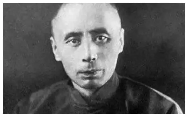
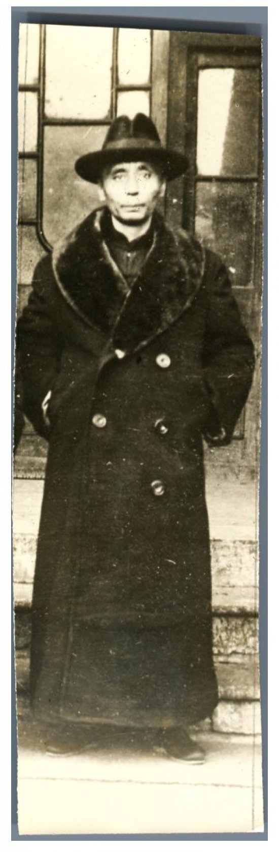
在这些汉奸中,臧式毅应该算是个悲剧性人物。他的投敌大有不得已之处。
臧式毅(1885—1956),字奉久,原籍山东诸城,生于辽宁沈阳。早年追随孙烈臣。后受张作霖及张学良赏识,任东三省保安总司令部中将参谋长、辽宁省政府主席等职。臧式毅是中国旧官僚中罕见的出色人物,东北易帜后,他出任辽宁省政府主席,任上大刀阔斧进行财政、金融改革,对此后东北的稳定贡献良多;尤可贵者,臧一生经手钱财无数,自己却两袖清风,在奉系集团中堪称异类,起初他在省城租几间瓦房居住,家徒四壁,后来张学良实在看不过去,觉得堂堂一省之长,如此寒酸,实在是“有辱奉系威名”,便自掏腰包为臧式毅购置了一套房子。“九一八”事变中,臧被俘后成为伪满洲国四巨头之一。日本战败后被苏联红军关押,后引渡回国,死于抚顺战犯管理所。
9月21日《盛京时报》大篇幅报道一消息,捏造说:“森冈领事往访臧式毅氏。臧氏颇示赞成。”意指奉张学良令留守沈阳的臧式毅赞成日军攻占奉天的行动。实际上,臧对日本人态度十分坚决。就在第二天,即9月22日,日本宪兵拘禁了臧式毅、教育厅长金毓敝和冯庸大学校长冯庸。
臧为人深沉练达,在张作霖被炸死的时候,他是东北军在关外的实际军事负责人。紧张局势之下,臧为主谋,瞒天过海诈称张作霖仅仅负伤,哄骗日本方面,等待张学良入沈。并暗中整军待旦准备在日军有所行动时坚决迎击。当时,老萨的祖父在小河沿医院一带住,东北军就有军官便衣到那里视察地形,显然是准备必要时不惜和日军一战。在这种双管齐下的措施下,张学良才平安出关,完成易帜,中国得以统一。“九一八”事变前,臧准确判断日军即将启衅,曾多次向张学良告警,所获回答为张学良于9月6日给辽宁政委会代主席臧式毅,东北军参谋长荣臻发出的“鱼电”,称“对于日人无论其如何寻事,我方务须万方容忍,不可与之反抗,致酿事端……切实注意为要”。有鉴于此,才有1931年9月18日荣臻对北大营不抵抗的指示。“九一八”事变发生,臧式毅眼看局面已经无法挽回,一面流泪令荣臻等离开奉天南下,以图反攻,一面表示自己守土有责,不肯离去,试图与日方周旋,争取保住东北。臧随即被日军挟持,成为第一个被俘的中国省级大员。面对日军臧曾经冒死不屈,与日寇周旋四十余日。臧母也为深明大义之人,为他送物品时暗藏鸦片,意为劝子自尽。
但臧最终没有吃下母亲送来的鸦片,选择了屈服出任伪职。
这一举动被视为变节,遭到万人唾骂。但张学良晚年提到,臧出任伪职既非本心,也暗怀心事。他一方面以“联省自治”相抗日本人的“满洲国”计划,一方面秘密派人给张学良送信,进陈收复东北的方略和自己为内应的决心。但此时张学良身心两病,无心规复,臧之苦心遂翻成画饼。后来溥仪看出臧的用心,为了增强和日本人争夺权力的基础,在日人压力下放弃郑孝胥同时要求任命臧为国务总理。而日本方面对臧也早有警觉,遂强行推出亲日的张景惠。自此,臧被排斥出东北伪政权核心,并受到监视。他选择随波逐流,直到日本投降,自己作为伪满战犯被捕,亦无辩解之意。
前半生清正廉洁,一心为国;后半生被判汉奸,辩无可辩。或许,臧式毅的心里,惭愧与寒冷已经无可复加。
臧式毅的汉奸之名此生难洗,但是从他身上或许也会引发一声感慨——国家做得好些,哪来的那么多汉奸?
张学良将军亲口说过:“是我负了臧式毅。”
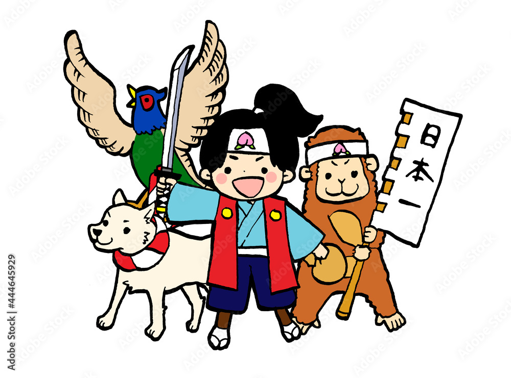
I was researching for a story backdrop for a game prototype. Preferably an adventure that involves traveling, making friends, and fighting evils. As someone who grew up in Asia, the first two that came to my mind was the Journey to the West (西遊記) and Momotarō (桃太郎). When I research further, I found some interesting articles about using a modified version of the story Momotarō as a propaganda tool in the colonial Taiwan.
Finding 1: 日本國民童話「桃太郎」在殖民地臺灣的傳播 LINK
Japanese citizen of country children’s story Momotarō expanse in colony Taiwan
本研究的起因是我第一次到臺灣的時候,碰到一位臺灣老人,她會說日文,因此本研究透過分析日治時期公學校國語教科書的童話「桃太郎」,藉以探討日本殖民政府的教育政策,以及日本教育對臺灣人的影響。
首先比較戰前日本的國語教科書和臺灣的國語教科書。分析在兩種國語教科書中出現的童話為何,並比較在日本民間故事和日本教科書中童話之差異點。
其次,爬梳日本國語教科書和臺灣教科書中的桃太郎故事。分析教科書所賦與桃太郎的意義。
最後,調查教科書以外的如報章雜誌及學校中學藝會、演講等使用桃太郎故事的情形,以分析桃太郎故事的擴散。此外,分別對8位受過日本教育的臺灣人訪談,分析他們對桃太郎故事的印象。
本研究認為,在日本五大童話中,桃太郎是具有日本特色,而且最容易操作的童話。日本殖民地時期,日本的教育關係者透過學校教育及各種管道,將帶有日本國民色彩的童話──桃太郎普及於殖民地臺灣,藉以教化臺灣兒童。
The motivation for this study originated from my first visit to Taiwan, during which I encountered an elderly Taiwanese woman who could speak Japanese. This inspired me to analyze the fairy tale Momotarō from the Japanese-language elementary school textbooks used during the Japanese colonial period, in order to explore the educational policies of the Japanese colonial government and the impact of Japanese education on the Taiwanese people.
First, this study compares prewar Japanese language textbooks with those used in Taiwan during the colonial period. It analyzes which fairy tales appear in both sets of textbooks and compares the differences between Japanese folktales as they appear in oral tradition and as they are presented in textbooks.
Next, it closely examines the Momotarō story as found in both Japanese and Taiwanese textbooks, analyzing the meanings assigned to the tale within these educational materials.
Finally, it investigates how the Momotarō story was used beyond textbooks—in newspapers, magazines, school arts festivals, speeches, and other settings—to analyze the tale’s dissemination. In addition, interviews were conducted with eight Taiwanese individuals who had received a Japanese education, to explore their impressions of the Momotarō story.
This study argues that among the five major Japanese fairy tales, Momotarō is the most characteristically Japanese and the easiest to utilize. During the colonial period, Japanese educators used school curricula and various channels to popularize the Momotarō tale—imbued with Japanese national identity—in colonial Taiwan as a means of instructing and assimilating Taiwanese children.
Finding 2: 战前中日两国间的桃太郎形象建构 LINK
桃太郎是全面抗战前中日两国重点关注的童话形象。日本建构的桃太郎形象始终围绕着“正义—桃太郎—日本”和“恶者—鬼—被征伐地区”的近代殖民文化逻辑展开。日本借助文人赴台宣讲、小学课本增列《桃太郎》、报刊宣传等方式,促成了桃太郎形象在中国台湾地区的普及、移植和变貌。但是,中国文人早已识破了日本对外殖民掠夺过程中以桃太郎为核心的“殖民合理化宣传”陷阱。如章太炎批判了此故事蕴含的侵略意念,启发了芥川龙之介改写桃太郎并揭露日本“桃太郎主义”中的伪善正义;连横追溯了桃太郎的汉文化传统、展现出浓厚的民族认同和家国情怀;杨逵则提炼出桃太郎故事的左翼精神,主张积极践行“行动主义”, 激发劳苦大众勇于抗争殖民掠夺和阶级压迫。
Before the full-scale war between China and Japan, Momotarō was a prominent fairy tale figure closely followed by both countries. The Japanese construction of Momotarō consistently revolved around a modern colonial cultural logic that framed “justice–Momotarō–Japan” against “evil–demons–conquered territories.” Through means such as sending intellectuals to give lectures in Taiwan, adding the Momotarō story to elementary school textbooks, and promoting it via newspapers and magazines, Japan facilitated the popularization, transplantation, and transformation of the Momotarō image in Taiwan.
However, Chinese intellectuals had already seen through Japan’s use of Momotaro as a tool of “colonial justification propaganda” in its external expansion. For example, Zhang Taiyan criticized the story’s underlying message of aggression, which in turn inspired Akutagawa Ryunosuke to rewrite Momotarō and expose the hypocrisy in Japan’s so-called “Momotarō-ism.” Lian Heng traced the story’s roots in Han Chinese cultural traditions, expressing strong national identity and patriotic sentiment. Meanwhile, Yang Kui extracted a leftist spirit from the tale, advocating for proactive “activism” and encouraging the working class to courageously resist colonial plunder and class oppression.
Reminds me of: Drop Your Whip (放下你的鞭子)
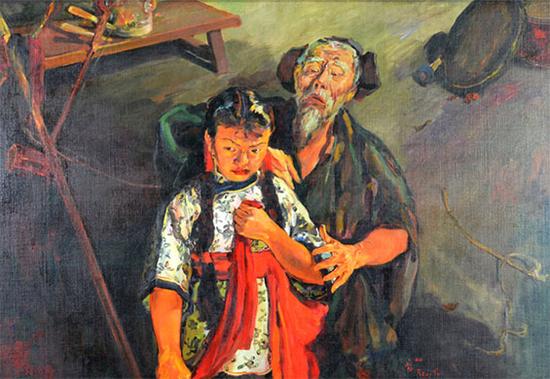
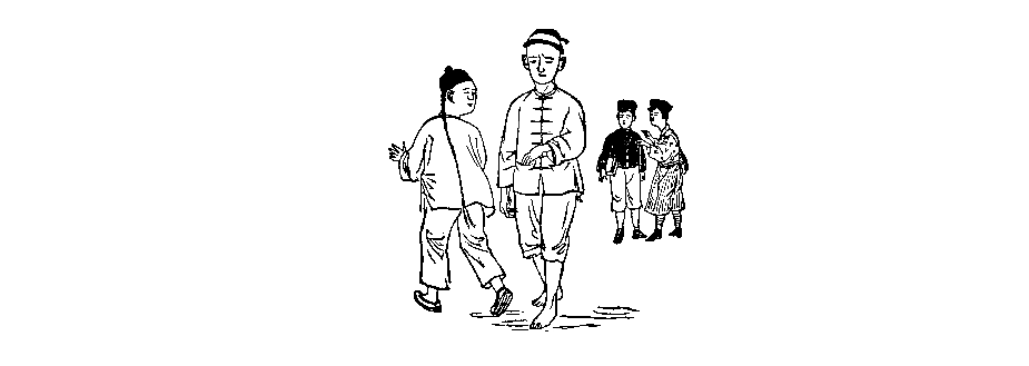
This reminds me of the street skit “Drop Your Whip” that I learned at the drama club in college. “Drop Your Whip” (放下你的鞭子) is a well-known Chinese street performance with propaganda significance, but it actually predates the Cultural Revolution and was later revived and repurposed during that period.
“Drop Your Whip” was originally a street skit (快板剧 or 小品) created in 1931 by dramatist Chen Liting (陈鲤庭) based on a play by Tian Han during the Anti-Japanese War era. The performance featured a young beggar girl being beaten by her stepfather. A passerby intervenes, scolds the stepfather, and gives the girl money. In the skit, the girl explains that her suffering is due to the Japanese invasion, not personal misfortune. This scene becomes a metaphor for national suffering under imperialism, encouraging anti-Japanese resistance.
During the Cultural Revolution (1966–1976), the piece was revived and adapted as revolutionary propaganda, often performed in public squares, workplaces, and rural areas. Its class struggle themes—a cruel oppressor (the stepfather) and a suffering innocent (the girl)—aligned neatly with Maoist ideology. The performance was used to foster revolutionary fervor, targeting both historical enemies (like imperialists) and class enemies within (landlords, counterrevolutionaries). In some cases, it was even staged as a criticism or denunciation session, with parallels drawn between the stepfather figure and actual individuals labeled as “class enemies.”
The “whip” came to symbolize oppression, and dropping it was a metaphor for overthrowing old systems—imperialism, feudalism, and capitalism. The emotional appeal, direct messaging, and performative nature made it effective for mass mobilization, especially in rural and less literate populations. Therefore, while “Drop Your Whip” wasn’t originally created during the Cultural Revolution, it became part of its broader repertoire of revolutionary propaganda, often adapted to fit shifting political narratives.


