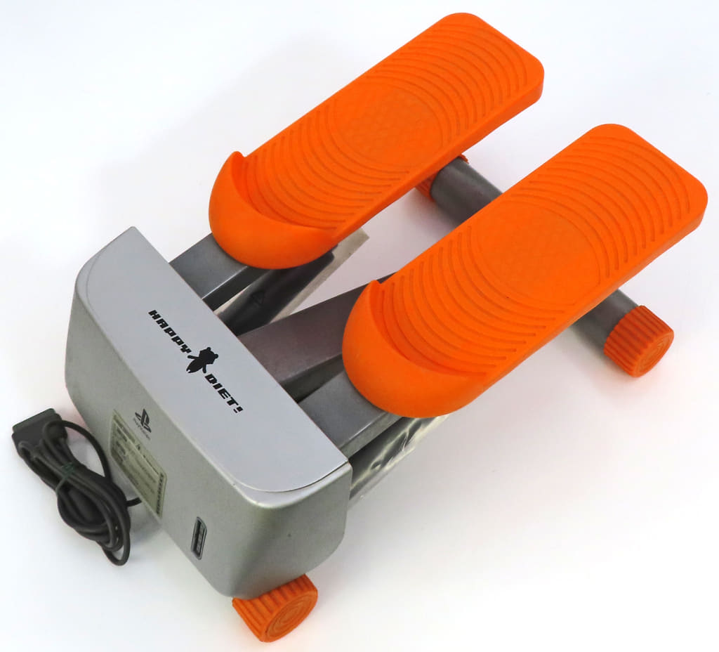
Happy Jogging In Hawaii
2001 Playstation

ステッパーコントローラ(オレンジ)
ハッピーダイエット (Happy Diet) 対応
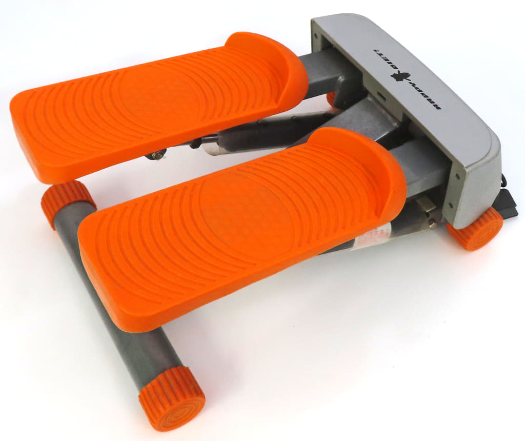
Happy Jogging In Hawaii
2001 Playstation
ステッパーコントローラ(オレンジ)
ハッピーダイエット (Happy Diet) 対応
NEW REMOTE WORKING OPPORTUNITY AVAILABE IN HELL!
Hell sure has become the popular destination in afterlife recently. In order to improve the overcrowded working condition, the bureau of labor in the underworld has open up to the idea of remote working. This is a pilot program for monster walkers in hell which is similar to dog walkers here. If you have received one of these kits at your doorstep, congratulations, you are going to hell soon, and you better set it up and start working, those hell hounds won’t walk themselves!
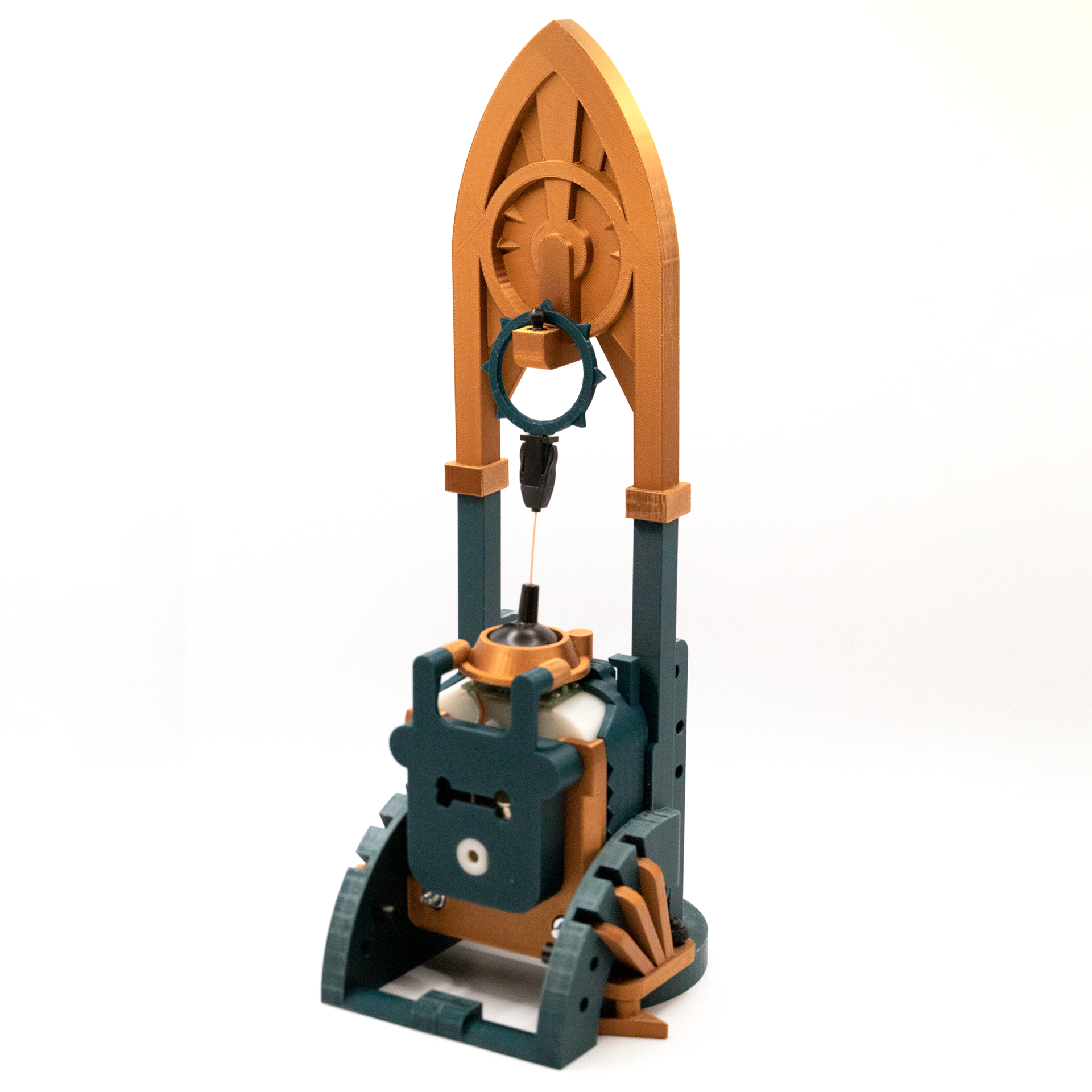
This is a single player experience made possible with a custom alternative controller which allows the player to walk a hellhound on a leash. People who work remotely as a hell hound walker will receive a remote working kit. Inside the kit, there is some kind of a monitor, a specialty controller (the Leash), manual, power adaptors, and some AV cables.
The Leash controller is made of a repurposed Gametrak 2 joystick module. I have been wanted to upcycle Gametrak 2 controllers for something fun since it came out. It is essentially a physical motion tracker. It is a brilliant idea from other side of the pond. It is a wonderful controller, especially the 2nd version with modular joysticks which I incorporated in my controller. I also loaned it to my students from time to time just to see what came up. Here are two fun examples:
Echo Rift by Yi-Ning Huang, Clover Paradise, Pierce Wolcott, and Hang Ye, 2014.
This experience puts players into the shoes of a bat navigating a virtual cave. By tilting and turning the oculus, users could control their trajectory as they glide past stalactites and stalagmites. Using a Gametrak controller modified to be wearable, players could also influence their altitude by flapping their arms. This resulted in surprisingly immersive experience, that was also lots of fun to watch.
https://piercewolcott.com/portfolio/echo-rift/
Group Project Assignment 1 by Luca Jeha Civita and Krystal Huang, 2023.
We decided to create an instrument using the Gametrak string sensors Kyle showed us in class. We pictured something that allowed for rhythm, harmony, and melody.
https://new-arcade.tumblr.com/post/732013080328929280/luca-krystal-progress-report
Since this is supposed to be an tool sent from hell, I am trying to make the alternative controller looks like an ancient religious artifact from a sci-fi movie or Warhammer 40K — that dark, gothic, and futuristic look and feel. Most of parts are connected or glued together with Lego Technic friction pins (#2780). The base are hold together securely with a hair loop which is a technique I used frequently with my builds.
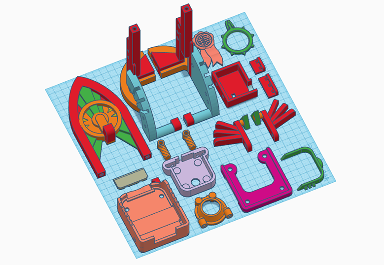
The enclosure for the Gametrak 2 module has gone through many iterations. The original design was meant to work with M5Stack Fire and its sensor units, so I designed thicker wall to accommodate the Lego Technic pins. I moved on to a simpler Arduino setup because the analog data are more reliable for what I am doing. I am able to reduce about 5mm (back plate) + 3mm (front plate) of the thickness which helps the controller and the leash align with the hook on top better.
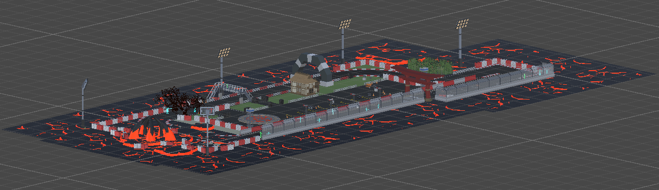
For the aesthetics, I am imagining each level is a park in hell. There will be lost souls, ghosts, monsters, magma everywhere, typical hell stuff. The first park is an abundant race track that I modified from a Synty game asset that I own and remixed it with all the hell elements above.
The missing piece:
https://www.frathwiki.com/Parseltongue-inspired
List of Game assets used in this prototype:
Mix of Synty Game Assets
https://syntystore.com/
Demon Dog
https://assetstore.unity.com/packages/3d/characters/creatures/demon-dog-122346#publisher
Simple Racer – Cartoon Assets
https://assetstore.unity.com/packages/3d/vehicles/land/simple-racer-cartoon-assets-37490
Oak Forest (Tree Pack)
https://skfb.ly/oOrvE
The ambience sound 1 was a loop sampled from
-D&D Ambience | Hell | Cries, Agony, Despair, Demons, Devils, Magma, Avernus
https://youtu.be/JzVIkY5tKcE
The ambience sound 2 was a loop sampled from
10 Hours Lava Flow, Kilauea Hawaii
https://youtu.be/kTpglKDyn4s
Dan visited DT in 2018 when he was an evangelist at Unity. He did a demo for us on Unity’s latest cinematic pipeline at the time. Can’t believe it was almost 7 years ago! I reached out to Dan for some insights on how much we will be able to accomplish with Unity Visual Scripting and VisionOS.
… it’s been a really fun project. There has been some work to support visual scripting in AR Foundation but mostly from a mobile perspective. The good news is that most of those API’s are the exact same on mobile as on VisionOS.
So there are some visual scripting nodes and logic is supported for accessing ARKit data (through AR Foundation). The challenge will probably be understanding how and where ARKit on iOS differs from ARKit on VisionOS (it’s a very small subset of the features supported on iOS). Then creating custom logic to fill those gaps or access the data differently. Lastly input will likely be a challenge as there are some unique constraints to how VisionOS handles input.
STYLY-VisionPro-30Days:
https://github.com/styly-dev/STYLY-VisionPro-30Days
OSC Jack
-> OscJackVS
-> WebRequest Visual Scripting
-> PolySpatial Environment Diffuse Shader
-> Spectrum Visual Scripting Nodes
-> UniGLTF
-> VRM-1.0
-> VRM Visual Scripting Nodes
com.unity.cloud.gltfast.Currently stuck on Day 3.
FAQ

original documentation:
https://learn.adafruit.com/mini-thermal-receipt-printer/overview
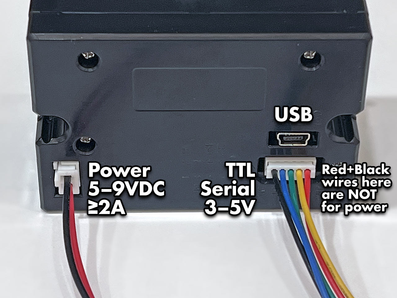
The Tiny printer has three sockets: a 2-pin connector for power, 5-pin for TTL serial communication, and a USB port. DO NOT attempt powering from the red and black wires of the serial cable. This cable is not following common electronics color conventions and connecting power here may damage the printer! Use ONLY the 2-pin connector for power.
Most of these thermal printers have a test feature providing basic diagnostics. You’ll then know that power is good, paper is correctly loaded, and have some configuration details of the particular unit.
On most Mini and Tiny printers: hold down the button on the top of the printer while connecting power to print a test page. In normal use, tapping this button feeds the paper by one line.
The Tiny printer data cable has five wires:
*The above description is not true to my Tiny Thermal Printer, my black wire is ground. It is labelled at the bottom of the printer.
This is in addition to the separate power cable, described on the prior page.
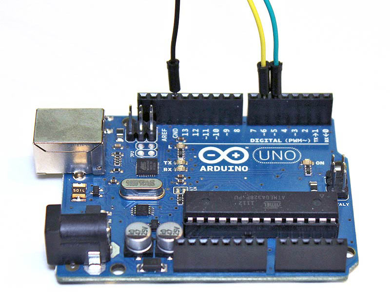
For a board like the Arduino Uno, the other end of the jumper wires can insert into the board edge sockets. For smaller devices on a breadboard, insert into the corresponding contact strip.
Ground from the printer always connects to GND on the microcontroller board. For the data wires (TX and RX), which pins to connect to can vary by hardware and software, explained further on subsequent pages. Some situations may require specific pins, but you can usually use any two pins. Here’s the printer’s TX line connected to digital pin 5, and RX to digital pin 6:
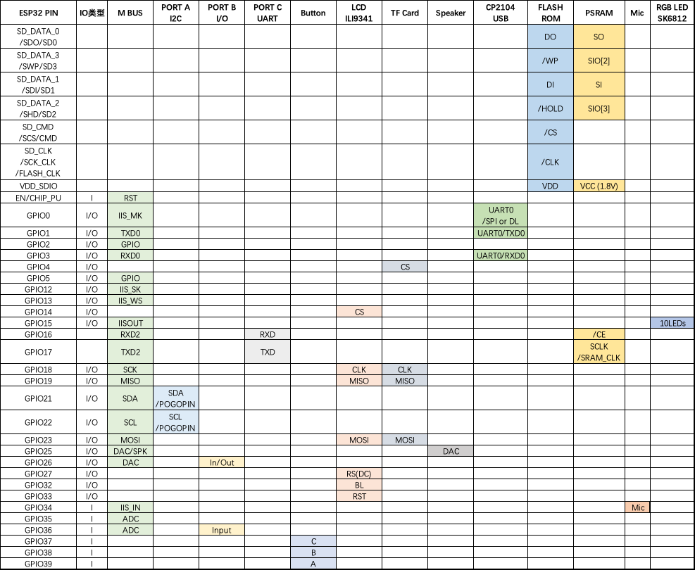
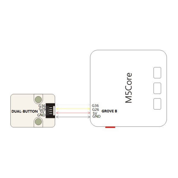
GPIO 36 is INPUT ONLY, so rx has to be 36
Connections are explained on the prior page. For the Arduino example code, we’ll connect the printer’s data out (TX) wire to digital pin 5, and data in (RX) to digital pin 6. Ground can go to any Arduino GND pin. Pins are configurable, but this is what the example uses, so let’s stick with that for now.
On the Arduino side, pin 5 receives (RX) and 6 transmits (TX)…opposite of the printer’s pin functions…called a crossover configuration, something you’ll hear a lot in serial communication and networking.
Install Library
We made an Arduino library to assist working with these printers.
Go to the Arduino Library Manager under Sketch→Include…Library→Manage…Libraries…
Search for and install the Adafruit Thermal Printer library
You should now be able to access the sample code by navigating through menus in this order: File→Sketchbook→Libraries→Adafruit_Thermal→A_printertest
If your printer test page shows ‘BAUDRATE: 9600’, you’ll need to make a small change to the library source code. Using a text editor (Notepad, etc.) open the file Adafruit_Thermal.cpp and change this line:
#define BAUDRATE 19200
Some printers arrive from the factory set for 19200 baud, but a few may be set to 9600. This will not negatively impact the performance of your unit! The speed of the paper through the printer is already much less than this and you will not see any difference…it’s strictly a data protocol issue of getting the microcontroller and printer communicating.
Two places in the A_printertest sketch have to be modified to work with M5Stack Fire:
OK upload the sketch (with baudrate change if necessary) to the Arduino. You should see the printer print out the example receipt which includes all the capabilities of the library.
The thermal printer has a few handy things it can do, most of which are in the A_printertest sketch. These are shown in the image above. In order, starting from the top:
Look through the source of the A_printertest sketch to see these used in context.
This printer can produce bitmaps, which can add a touch of class to a receipt with your logo or similar. Resolution: 8 dots/mm. 384 dots/line;
The first step is to get the image prepared. The printer can only do monochrome (1-bit) images, and the maximum width is 384 pixels. We suggest starting with a small bitmap (100 pixels or less on each side) and then experimenting to get the size and look you want.
A few steps are required to prepare an image for printing. For Windows users, there’s a nice graphical user interface for this. For Mac and Linux, different tools are used…not as visually slick, but they do the job well.
[Caution] These barcode printers shouldn’t be confused with a LaserJet – they’re not good at printing heavy/dense images with lots of black or they might stick and stall!
Use an image editing program to save your image as a 1-bit BMP — in Windows, the built-in Paint program will suffice.
Download, install and run LCD Assistant (https://en.radzio.dxp.pl/bitmap_converter/). This program is for Windows only but does a really fantastic job! Load the BMP file you previously generated (in Paint, etc.). The file must be in BMP format — the software won’t read PNG, GIF, etc. Then a couple of settings need to be adjusted…
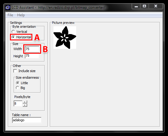
First, in the “Byte orientation” section of the settings, select “Horizontal” (item A in the image above).
Second (item B above), you may need to change the Width setting. Because this software (and the thermal printer) handle images in horizontal groups of eight pixels, if the image width is not a multiple of 8, it will be truncated (cropped) to the nearest smaller 8-pixel boundary. For example, with the 75 pixel wide image above, the output will be cropped to only 72 pixels wide, losing some data from the right edge. To avoid this, increase this number to the next multiple of 8 (that would be 80 for the example above), and the output will be padded with blank pixels to cover the gap. Remember the number you use here, you’ll need it later.
The image height does not need to be adjusted this way, only width.
Set the table name to something short but descriptive (e.g. “adalogo” above), then select Save Output from the File menu. Give the file a similarly brief but descriptive name, ending in “.h” (e.g. “adalogo.h”).
To get this file into your Arduino sketch, select “Add File…” from the Sketch menu. This will add a new tab to your code. Your original code is still there under the leftmost tab.
A couple of small changes are now needed in both tabs. First, at the top of the file containing the new table data, change “const unsigned char” to “static const uint8_t PROGMEM” as shown below:
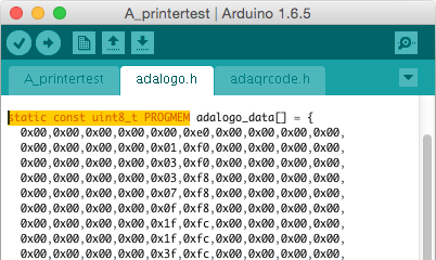
Next, in the tab containing the main body of your code, add an “include” statement to reference the new file:
#include “adalogo.h”
Check the A_printertest example sketch if you’re not sure how to include the code properly.
You can now output the image by calling printBitmap(width, height, tablename), where width and height are the dimensions of the image in pixels (if you changed the image width to a multiple of 8 as previously described, use that number, not the original image size), and tablename is the name of the array in the new tab (e.g. “adalogo” above).
Having a graphical user interface is nice, but some of these extra steps can be confusing and error-prone. If you prefer, the technique below for Mac and Linux works in Windows as well.
Thermal printers are really good at printing barcodes! This printer supports 11 different codes – UPC A, UPC E, EAN13, EAN8, CODE39, I25, CODEBAR, CODE93, CODE128, CODE11 and MSI. It only supports linear (1-D) barcodes, and can’t generate 2-D barcodes like QR codes (although there is a hack you can do, see below!) Barcodes are generated “on the fly,” which is nice — you can customize the height and data included quite easily.
You can make a barcode by calling printBarcode(“barcodedata”, BARCODETYPE), where the first string is the data to encode (e.g. a UPC code) and BARCODETYPE can be UPC_A, UPC_E, EAN13, EAN8, CODE39, I25, CODEBAR, CODE93, CODE128, CODE11 or MSI.
Some barcodes are very restricted — you can only put in 12 numbers, no characters. Others are very flexible and take nearly any character input. Please check out the wikipedia list detailing kinds of barcodes to pick the right one for your application.
The available range of barcodes varies with the printer firmware revision. Check Adafruit_Thermal.h for a list of codes.
It’s also possible to print QR codes, if you’re willing to pre-generate them. This might be handy if you want to, let’s say, include a URL on the receipt and the URL doesn’t change. You can generate QR codes at many sites including this one. Use the smallest QR code size. The image will be in PNG format, so if you’re using the Windows LCD Assistant tool you’ll need to convert it to BMP first (Windows Paint works for this). Then you can convert and embed this in your Arduino sketch as previously described.



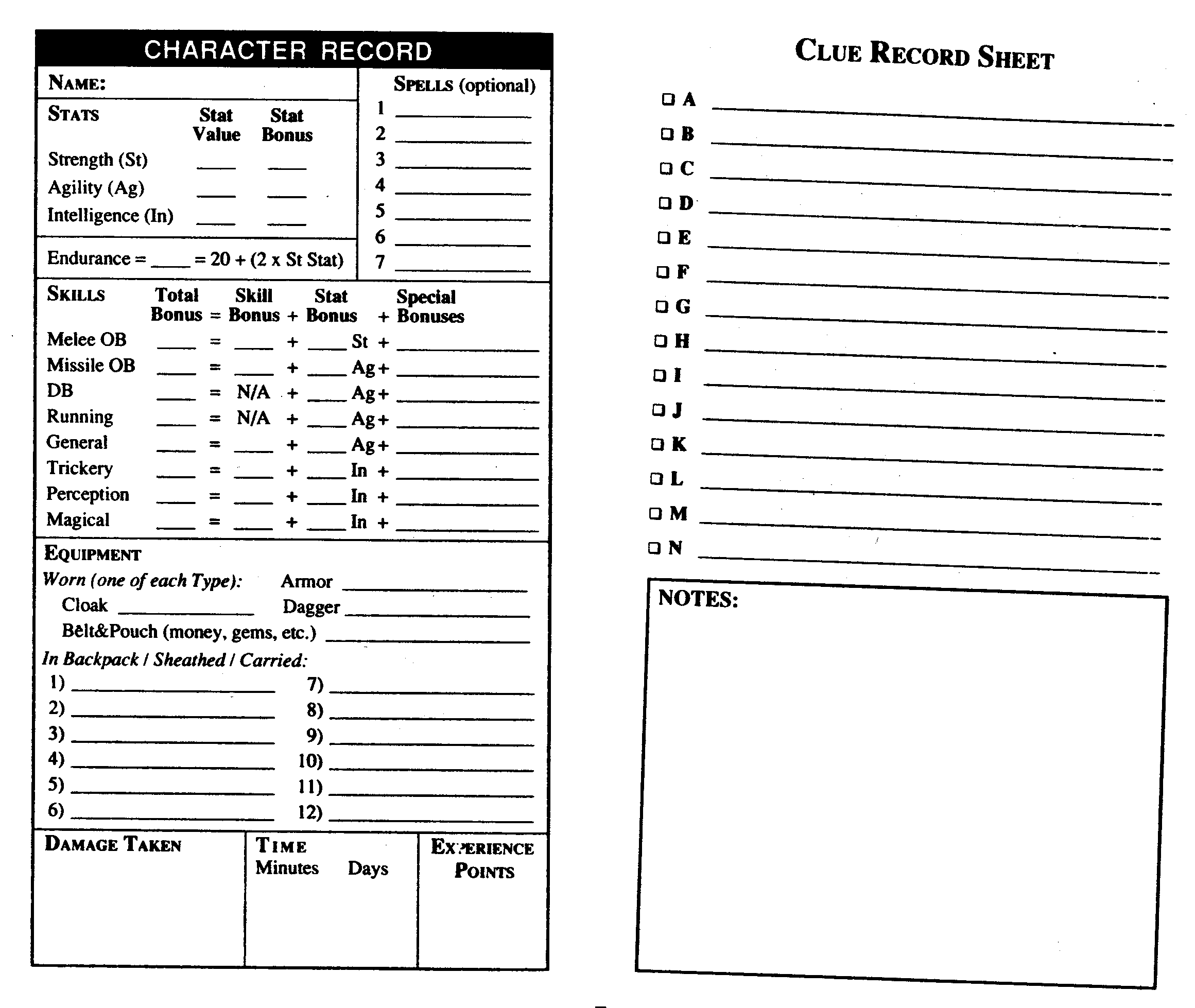
1. Night of the Nazgûl
2. The Legend of Weathertop
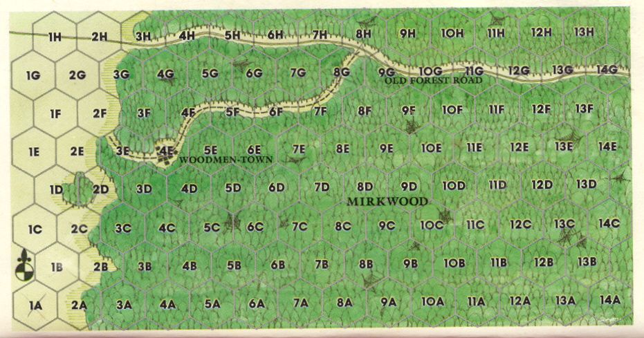
3. Rescue in Mirkwood
4. Murder at Minas Tirith
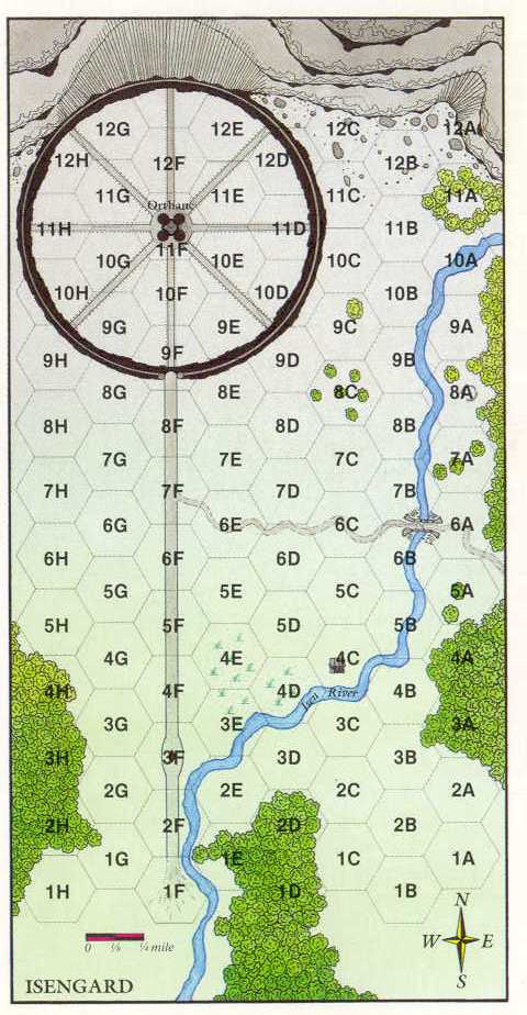
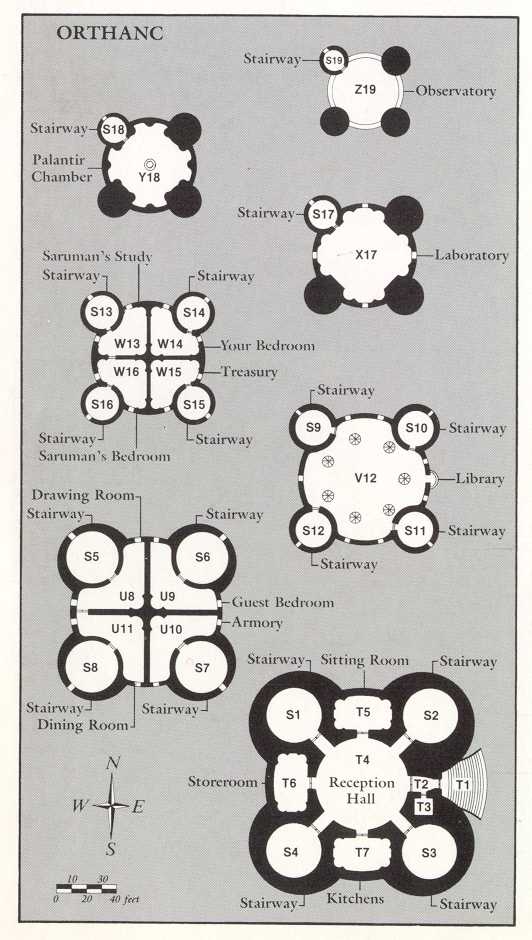
5. A Spy in Isengard
6. Treason at Helm’s Deep
7. Mines of Moria
8. Search for the Palantír
9. Race from Rivendell
10. Pirates of Pelargir
11. Lost in the Lonely Mountain
12. Quest for the Palantír: The Ruins of Annuminas
13. Mission to Mordor
In Traveling Witch, the player brews potions to bring happiness to people around the world. The game provides a portable cabinet full of wicked ingredients and a half-sized cauldron that hasn’t been cleaned for generations. Players have to figure out what potion to brew based on their conversations with visitors.
The physical controller playset was designed to simulate the act of brewing potions. Based on conversations with visitors, players refer to their notes (the clue book), select the correct ingredients, and stir the cauldron in a particular way to complete the potion. These physical interfaces provide an intuitive, tactile experience that elevates the gameplay’s sense of playfulness and immersion.
Here is a video without the physical clue book:
https://www.instagram.com/p/C3OfLvORXUd
I made a cauldron controller in 2020 (here). Originally, the controller was meant to do two things — read multiple ingredients (RFID tags) and use stirring motion (KY-040) as an input. The multi-RFID reader board wasn’t that reliable at the time. Depends on how the RFID tags was stacked, not all tags were read properly. However, stirring both clock and counter-clock wise was working and felt very satisfying. I have wanted to build an example of a simple ID system, I decided to come back to the cauldron and try a different approach to id the ingredients.

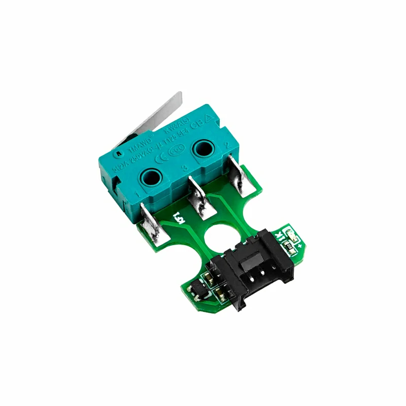
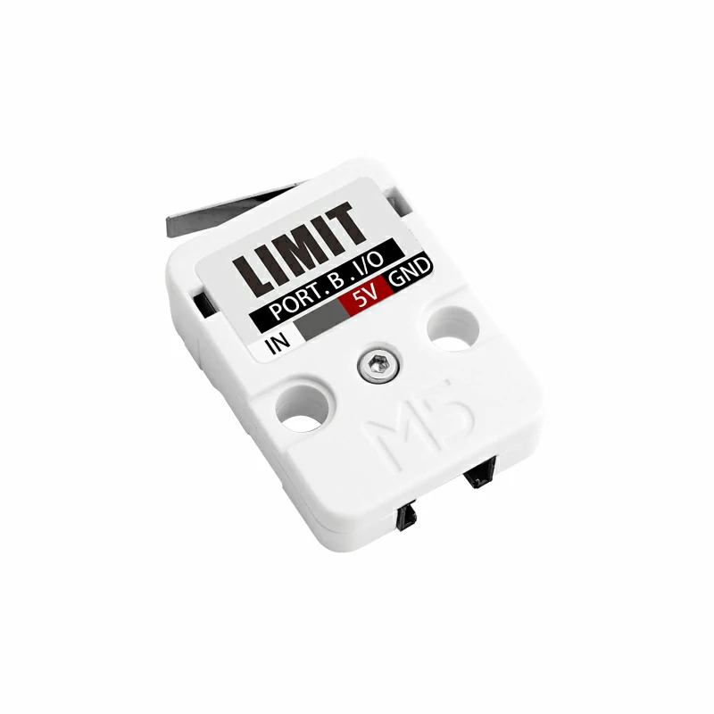
The old cauldron was made of KY-040 and Adafruit Feather. I decided to build the ID input module and cauldron with M5Stack this time because a stack of Limit Switch units (SKU: U145) is perfect for creating a simple ID system. I made the ID input module in the form of an alchemy cabinet. The player can insert the ingredient data card from the top of the cabinet and press down to send in ID. Switch-based ID system is a simple but effective method used in many interactive toys. Every switch has an on and off state. I used 5 switches to create 2 to the power of five -1 IDs for this play experience. -1 is because 00000 won’t work in my setup. I am only using 5 ingredient data cards at the moment.
M5Stack Fire Document:
https://github.com/m5stack/m5-docs/blob/master/docs/en/core/fire.md
Working with the M5Stack unit – Limit Switches:
I wanted to create an ID system using 5 limit switch units. However, I found out only 4 of the 6 ports on pHub unit can be used as digital inputs. The rest two are analog only. This is not a road blocker, it only makes reading switches a little more complicated.
https://shop.m5stack.com/products/limit-switch-unit
Working with KY-040:
I started out with the basic example code that can be easily found on the internet. There were little unwanted jumps on directions here and there, but it was acceptable. However, when I started to add more code to the sketch, the amount of jumps increased drastically. At first, I had suspected it might have something to do with debouncing. The amount of jumps remains the same after trying both software and hardware debouncing. I then found out the code I added to the sketch, especially in the loop(), slows down each loop cycle by about 6 ms compared to close to 0 ms with just the KY-040 example code. I eventually found a workaround using interrupts which in a nutshell is like threading for Arduino. It works perfectly without any jumps on directions when stirring the cauldron.
https://github.com/ownprox/Rotary_Encoder_KY-040_Fixed/
3D models – Medicine Cabinet

3D Model – Cauldron

What goes into a witch’s cauldron?
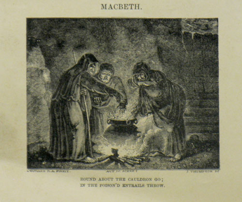
Macbeth, Act IV, Scene I (William Shakespeare 1564 – 1616)
The three witches, casting a spell
[First Witch]
Round about the cauldron go; In the poison’d entrails throw. Toad, that under cold stone Days and nights hast thirty one Swelter’d venom sleeping got, Boil thou first i’ the charmed pot.
[All]
Double, double toil and trouble; Fire burn and cauldron bubble.
[Second Witch]
Fillet of a fenny snake, In the cauldron boil and bake; Eye of newt, and toe of frog, Wool of bat, and tongue of dog, Adder’s fork, and blind-worm’s sting, Lizard’s leg, and howlet’s wing, For a charm of powerful trouble, Like a hell-broth boil and bubble.
[All]
Double, double toil and trouble; Fire burn and cauldron bubble.
[Third Witch]
Scale of dragon, tooth of wolf, Witches’ mummy, maw and gulf Of the ravin’d salt-sea shark, Root of hemlock digg’d i’ the dark, Liver of blaspheming Jew, Gall of goat, and slips of yew Sliver’d in the moon’s eclipse, Nose of Turk, and Tartar’s lips, Finger of birth-strangled babe Ditch-deliver’d by a drab, Make the gruel thick and slab: Add thereto a tiger’s chaudron, For the ingredients of our cauldron.
[All]
Double, double toil and trouble; Fire burn and cauldron bubble.
[Second Witch]
Cool it with a baboon’s blood.
Then the charm is firm and good.
These gruesome-sounding names are most likely used for dramatic effect rather than literal ingredients. For example, “Tiger’s chaudron” refers to tiger guts or entrails. However, when the ingredient is listed in modern analyses, it is interpreted to mean lady’s mantle, a common herb.
I thought I started with these 5: Hemlock root, toad, fillet of a fenny snake, eye of newt, and wool of bat.
The Clue Book:
Potions in Dungeons & Dragons:
https://www.reddit.com/r/DnDBehindTheScreen/comments/4btnkc/random_potions_table/
https://www.reddit.com/r/DnD/comments/2134j6/4e_crazy_and_fun_potion_ideas/
Interestingly, upon examining how D&D books might simplify potion recipes, I was struck by the remarkable similarity between potion-making and the practice of traditional Chinese herbal medicine.
Chinese herbal medicine utilizes ingredients derived from plants, minerals, and animals to restore balance and harmony to the body’s vital energy, or Qi. These components are typically combined into formulas tailored to an individual’s specific condition. Much like the exotic ingredients one might find in a fantasy cauldron, the herbs themselves often bear wonderfully imaginative names.
In order to prepare a Chinese herbal decoction, first soak the herbs in water for about 30 minutes. Then, boil and simmer the mixture for 45-60 minutes before straining the liquid. The process is repeated with the same herbs, using less water to extract a second, more concentrated decoction. The two liquids are combined to create the final drink. The brewing process and the end product is very similar to potion-making in my mind. The only notable difference from Chinese herbal decoction-making is the specific advice against using a cast iron pot which is what most cauldrons made of.

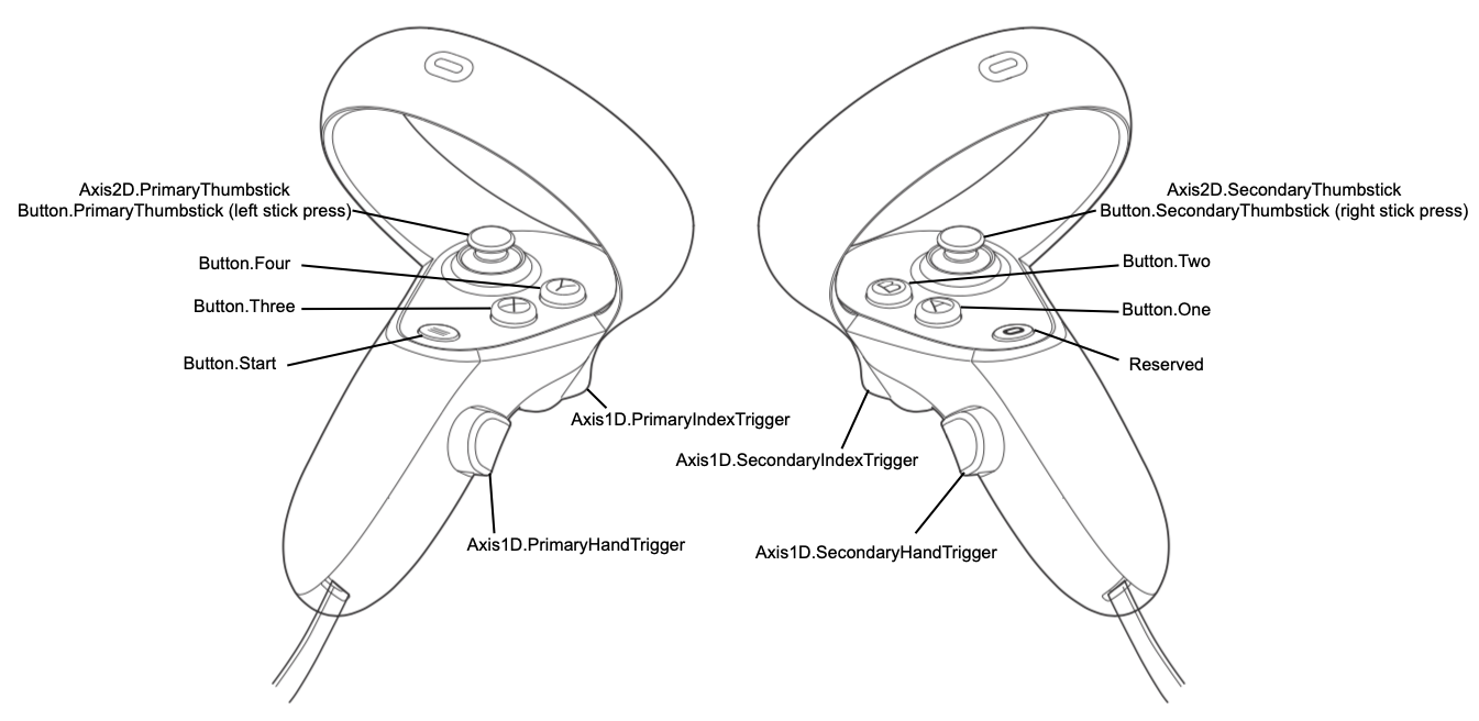
I had experimented with MR on Pico 4 but the resolution, image stitching, and controller tracking were not ideal. Since my code-free tool kit doesn’t support Meta 3 MR yet, I am going back to native OVR development for this experiment.
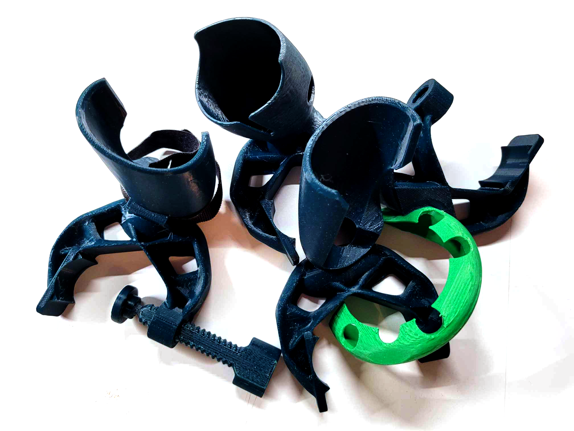
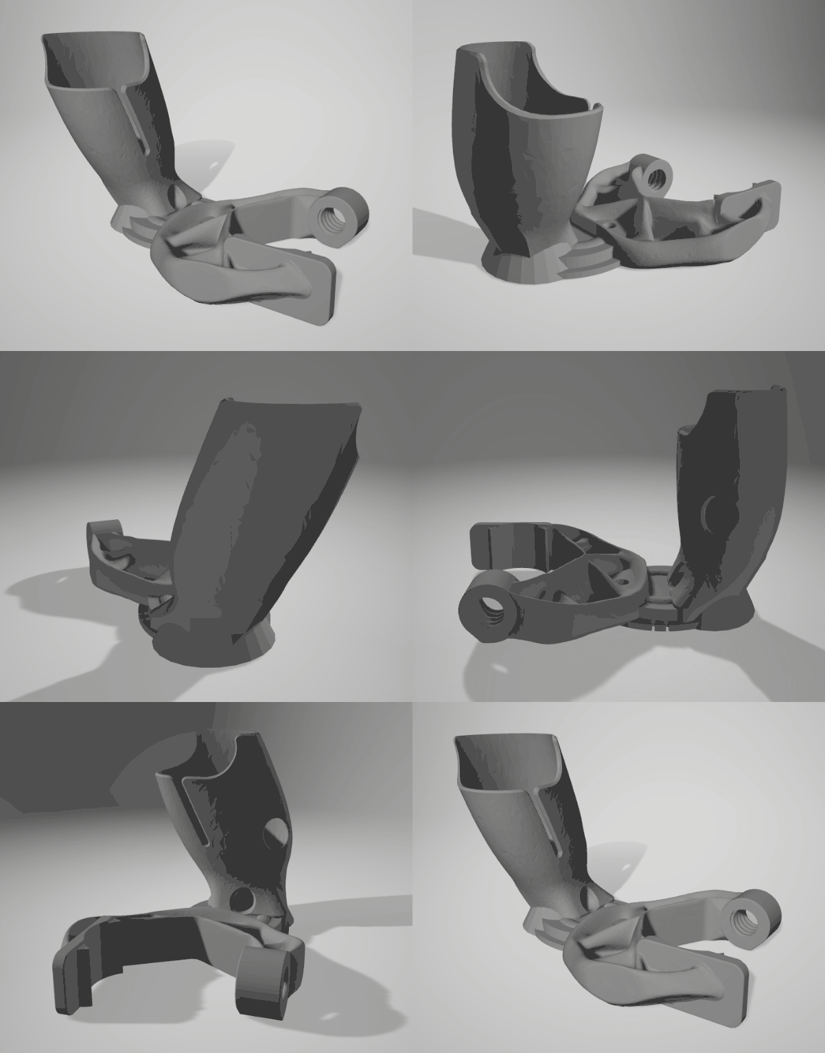
Quickly put together a clamp to mount the right touch controller on the Otamatone Deluxe. The final version was created by remixing the following parts together.
Prusament PET-G Clamp Optimized: https://www.thingiverse.com/thing:4158813
meta quest 3 – Simple gun stock V1.1: https://www.thingiverse.com/thing:6289919
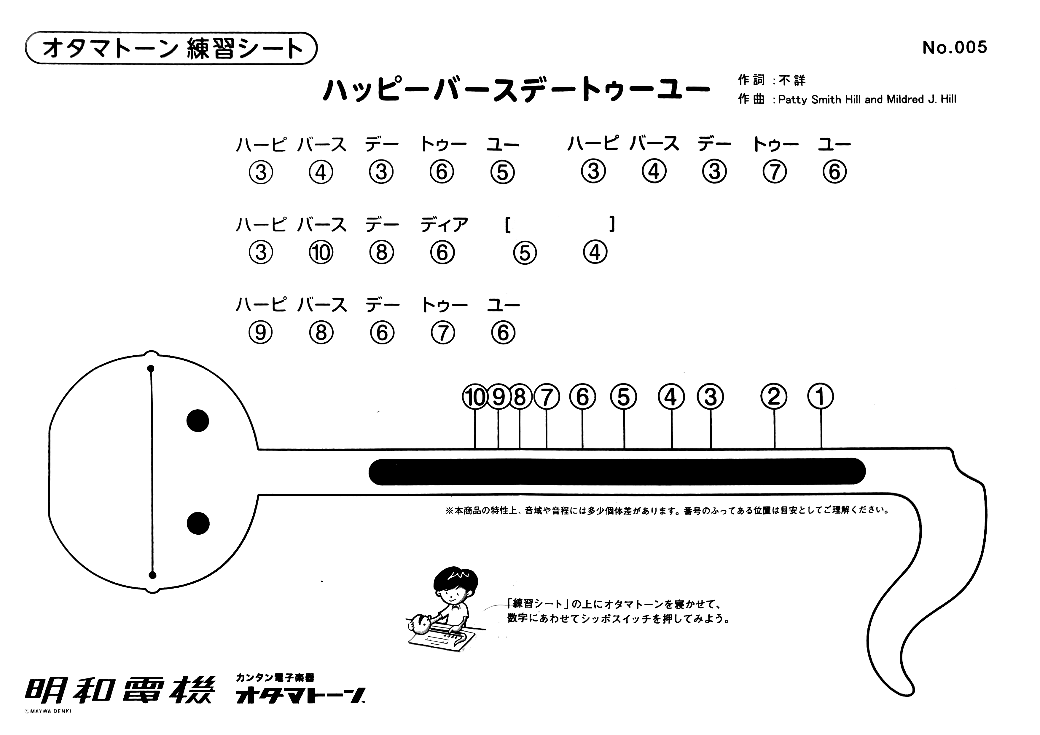
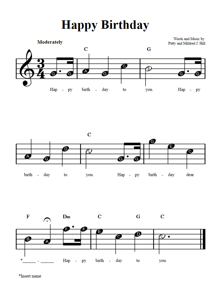
The first song that I am going to try is the Happy Birthday song.
The development is so much easier than I expected. This Youtube tutorial was really helpful.
Found a template project, work right away!
https://github.com/dilmerv/MetaAdvancedFeatures
First working prototype – me performing Happy Birthday!
View this post on Instagram
Even me can tell it was out of tune. The first prototype was based on a scale found on the internet. I decided to made one myself. I found out there are tuning apps available on my android phone. After testing a few free ones, I eventually found Tuner – Pitched!, it was free and didn’t have the complicated free trail model. I tasted it with a piano first, the app worked very well. My scale turned out to be very different than the one I used in the first prototype, and it sounds so much better! Maybe the scale I found on the internet was made for a different Otamatone model?

Now it finally sounds like it.
Okay, now I got the basic down, kinda, I am going to challenge myself with Le Festin from Pixar’s “Ratatouille”. The Cola Original Taste cover was super inspiring and made an impression of the song on me. Here is 10 hours of it.
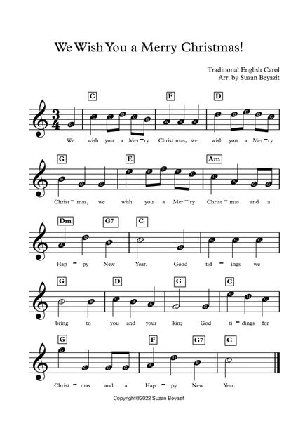
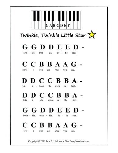

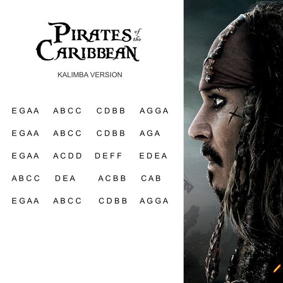
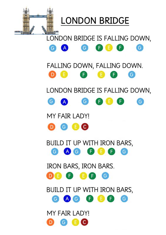
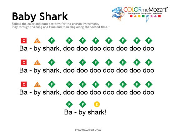
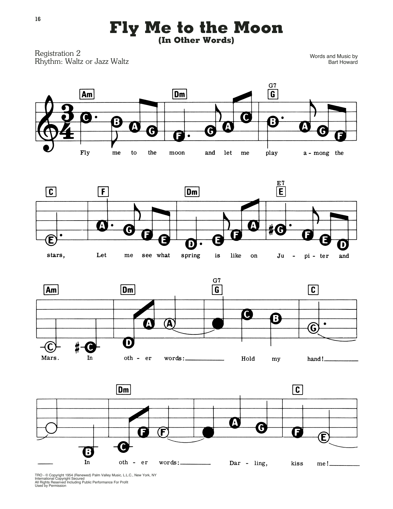
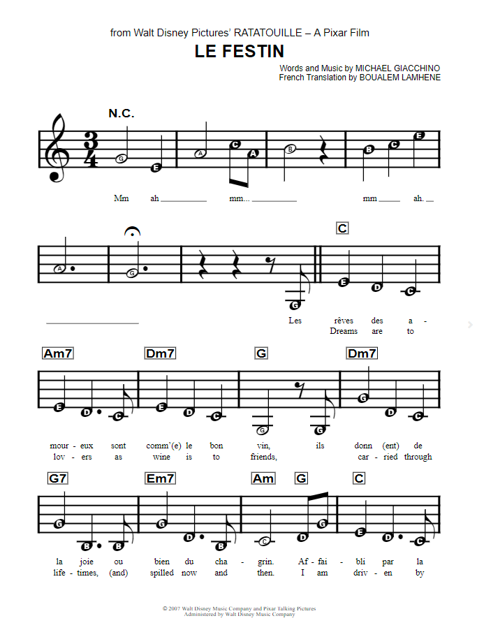
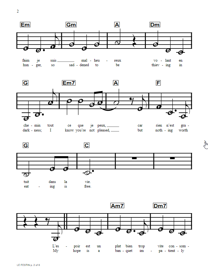
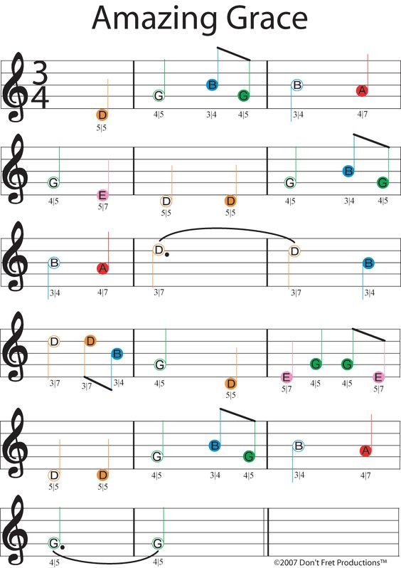
Music Math:
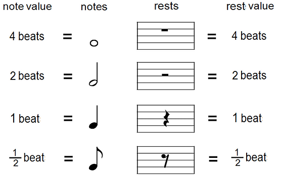
A whole note is held for 4 beats.
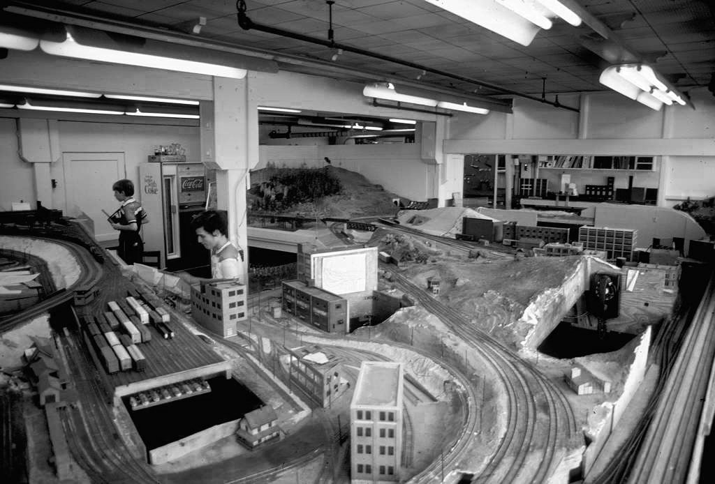
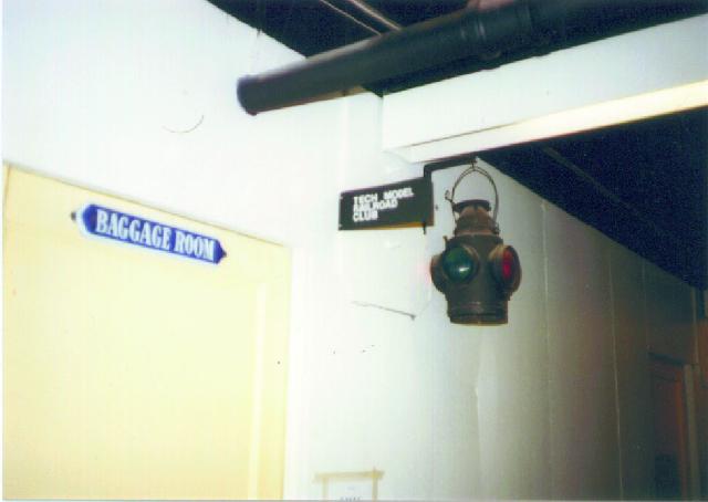
“Since TMRCies were known for their creativity and ingenuity Digital was kind enough to donate to TMRC the first PDP 11 to appear at MIT; this made the Club the first MIT student group to ever have a computer! Soon TMRCies combined the operation of WECo’s donations and Digital’s PDP 11 to create cab assignment and switching though the computer. The computer also allowed the implementation of ‘phone operation’ – that is, switches could be thrown via the telephone system within the club room! (This phone system, to be named MaRoto, was also a TMRC customized item.)”
http://tmrc.mit.edu/bldg20.html
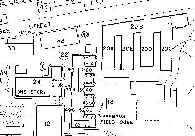
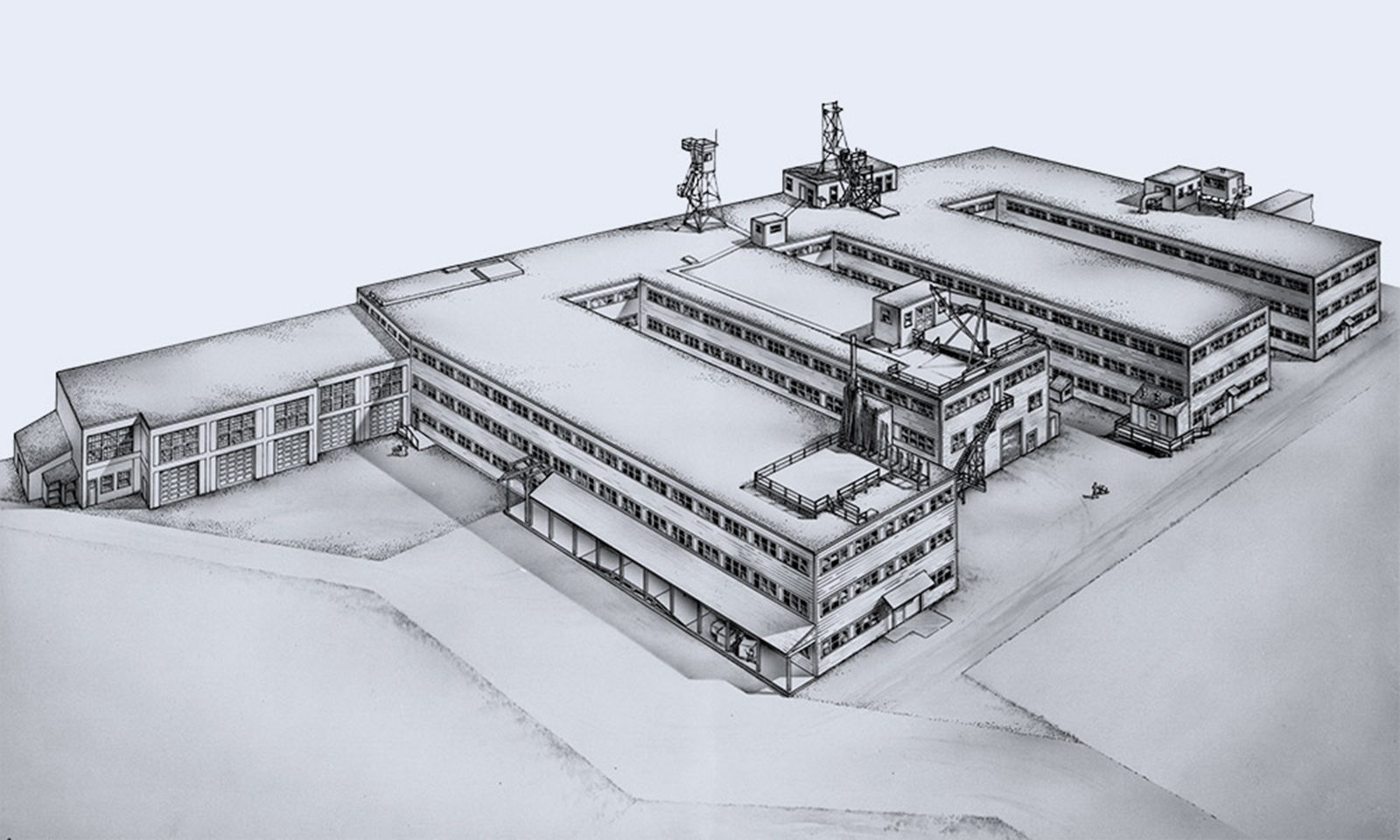
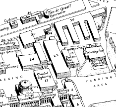
“Here’s what I found: the building was hastily-constructed of plywood. It leaked. It had bad acoustics and was poorly lit, inadequately ventilated, very confusing to navigate (even for people who had been working there for years) and was scorching in the summer and freezing in the winter.”

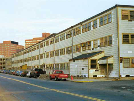
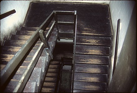


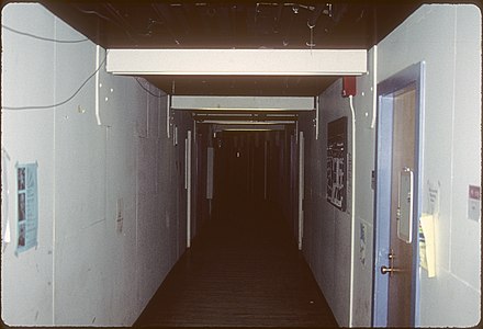
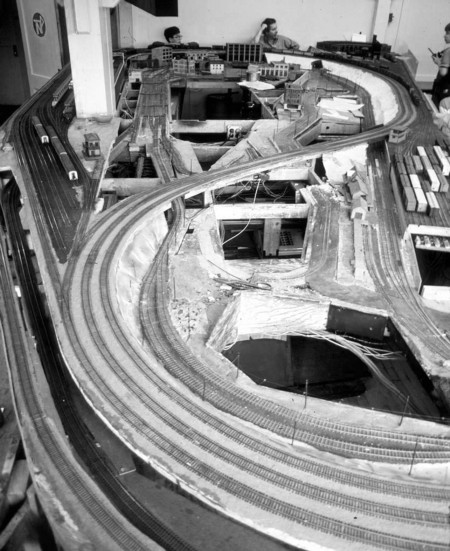
https://www.architects.org/stories/serendipity-when-walls-get-in-the-way
Occupants of Building 20 in 1963 (from Staff Telephone Directory, compiled by MIT Institute Archives)
Army, Military Science
Campus Patrol (20C-128)
Data Processing (20C-220)
Ice Research Lab (20E-206)
Industrial Hygiene Lab (20B-245)
Lab for Nuclear Science, linear accelerator (20D-014)
MIT Press (20B-120)
Model Railroad Club TMRC (20E-214)
Occupational Medical Services (20B-238)
Physics Labs
Research Corporation (20B-111)
Research Lab of Electronics
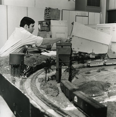
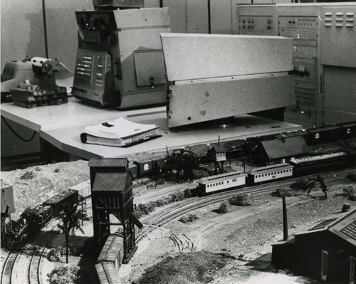
“The PDP-1 that originally went to Bolt, Beranek & Newman to be used in a more formal environment than at MIT was eventually retired to the University of Massachusetts at Amherst in 1968 during my own tenure there and was connected to a model railroad. It still had SpaceWar! as the primary program.
(J.A.N. Lee, ibidem, p. 272)”
https://wheels.org/spacewar/stone/rolling_stone.html
According to this link:
https://retrocomputingforum.com/t/the-tech-model-railroad-club-mit-1946-onwards-hacker-culture/3548
Posted by the user NoLand
Notably, the MIT wasn’t the only university which featured a model railroad, which also leads to a few confusions. E.g, in this context, we have to point out a couple of photos that are frequently distributed with the tag line “The PDP-1 at the Tech Model Railroad Club.”
Here’s one of them and even the CHM has it under the title “History – PDP-1 at the Tech Model Railroad Club” in its catalog.
There are some details that don’t add up. Notably, the PDP-1 was never at the TMRC and there wasn’t even a possible time window for this to happen. As it turns out, this is at the University of Massachusetts Amherst in 1968, and the person seen operating the PDP-1, which was indeed used to control the layout seen in the foreground, was J.A.N. Lee, Head of the then new CS program. The machine seen in the picture, is the PDP-1B production prototype that was originally installed at BBN in 1960 and was once used for Ed Fredkin’s pioneering timesharing system.
(Marginally interesting is that, while the machine had originally a detached operator’s console, this was now mounted to what looks like the integrated paper tape reader found on the production models, which it seems to have acquired over the years and which promotes a somewhat deplorable impression regarding the state of the computer, as if dismantled half-ways. BTW, the PDP-1 is the white (or rather cream colored) cabinets seen in the background of the photo. What’s balancing on the combined paper tape reader and console assembly may be a paper tape punch, as indicated by the rails around what looks like a slot seen at its top. The tape punch is the vertical slot seen at the right of the top front panel of the production models. — And, yes, as the machine retired to UMas, it was found to still have a copy of Space War in its non-volatile core memory.)
And, to close the circle, the image first publicly appeared (with a correct tag line) in a review of Steven Levy’s “Hackers”, the very book that popolarized the notion of the TMRC. This review was written by the same J.A.N. Lee, we see in the photo, and is found on page 271 of the Annals of the History of Computing, vol. 7, no. 3, July, 1985 (J.A.N. Lee, “Reviews: Levy, Steven. Hackers”, pp. 270-272).
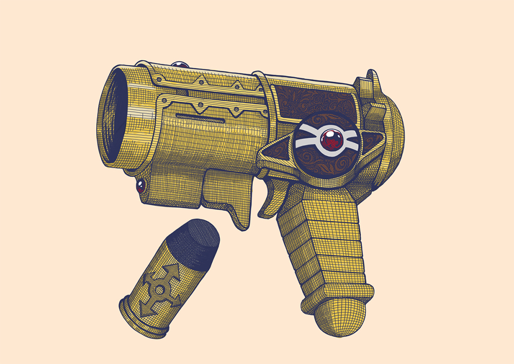
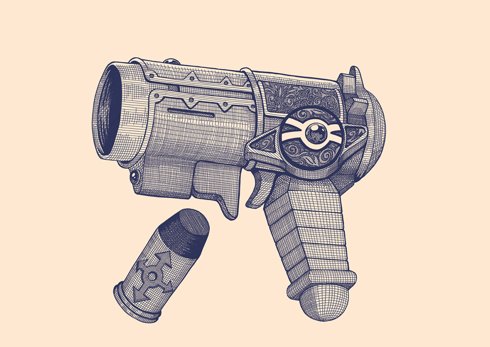
When I was reading Dragon Quest: The Adventure of Dai (DRAGON QUEST –ダイの大冒険–) as a kid, I had always fascinated by all the magic artifacts in the story. The magic bullet gun (魔弾銃) was my all-time favorite.

The gun belongs to Maam (マァム), one of the main protagonists in the story. It takes form of a gold-colored large-caliber single-shot pistol. There are a total of 8-10 bullets depends which version it is. For each bullet, a sacred stone that accumulates magical power is embedded at the tip, and by touching it and chanting a spell, it becomes charged with magic. The charged bullet can be loaded into the pistol from the the back by opening the tail cover, one bullet at a time.

After the defeat of Flazzard (フレイザード) on the island of Bulge, large firepower was needed to save Princess Leona (レオナ姫) who was frozen in ice by a forbidden spell. Because of this, Dai (ダイ) charged the bullet through his dragon emblem (竜の紋章), and although he was able to shoot it and melt the ice, due to the recoil from using a bullet with more power than the allowable amount. The gun barrel breaks in half. Badak (バダック), the self-proclaimed “King of Inventions,” tried to repair it, but it was broken beyond repair. Badak said, “Avan (アバン), who created this gun, was a genius.”. The Magic Bullet Gun was no more which is a pity.
Gun Visual No.1
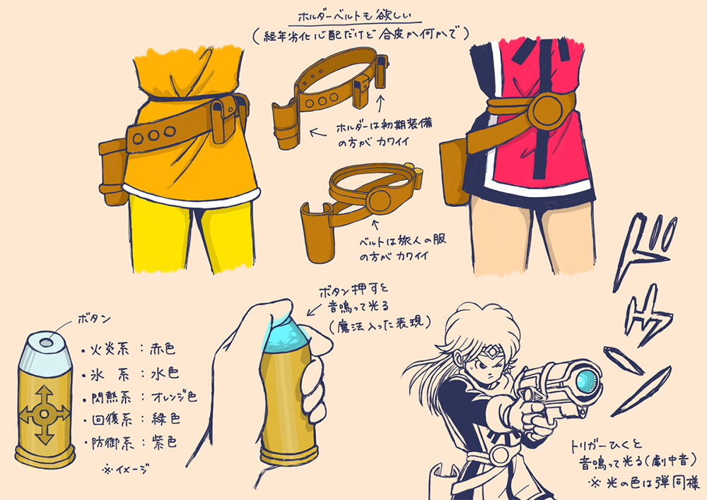
Gun Visual No.2

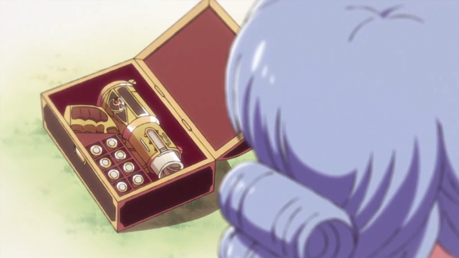
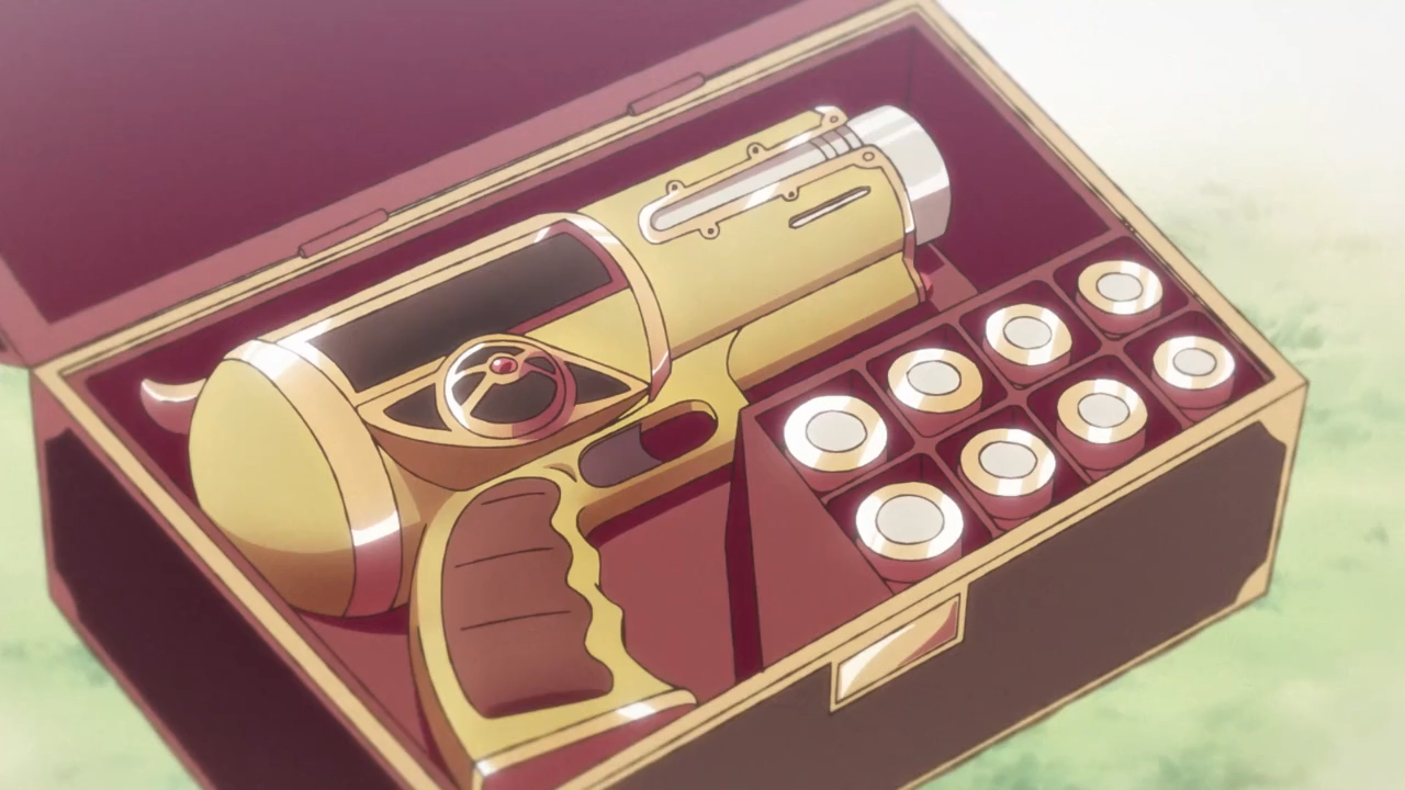
https://dic.pixiv.net/a/%E9%AD%94%E5%BC%BE%E9%8A%83
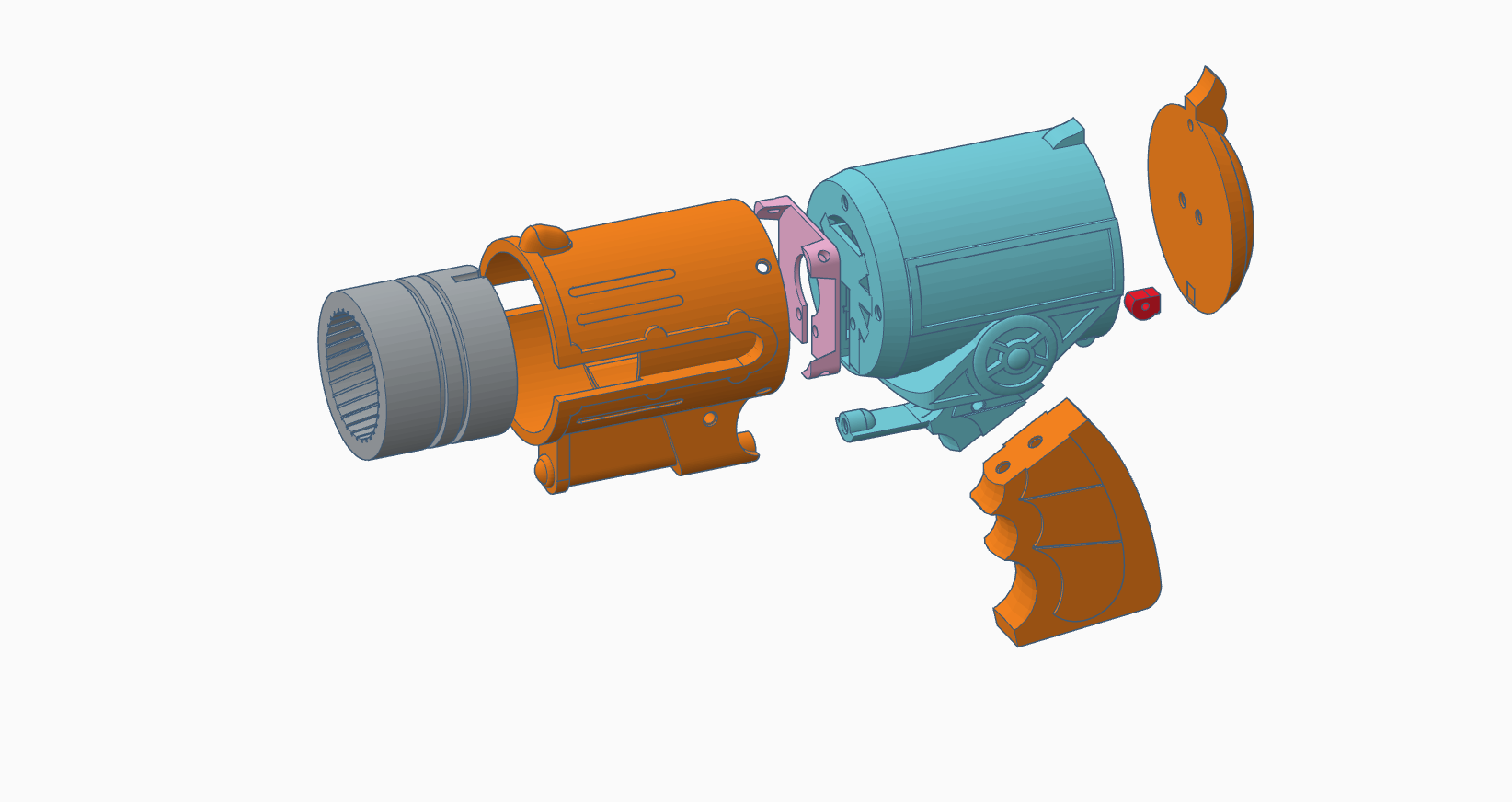
There are 2 major gun visuals. The biggest difference is the design of the trigger area and handle. Little torn here, because I like both designs. I am going to focus on Gun Visual No. 2 for this round because I had boxed out a prototype a while ago.
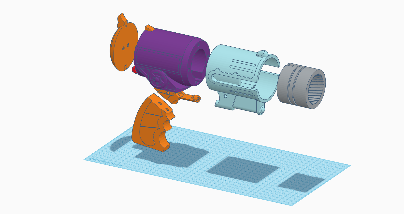
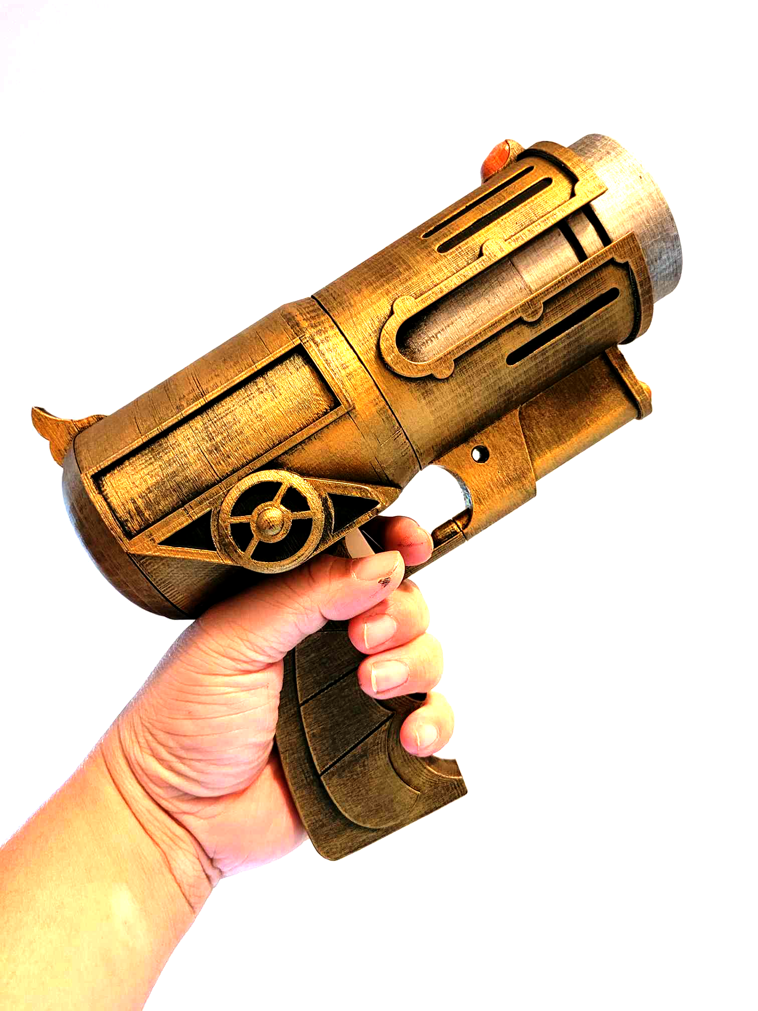
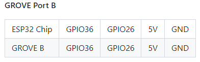
This is designed specifically to with M5Stack system. I did hack it a little so I can use the B port for both a limit switch unit (SKU: U145) and a Neopixel ring. I used a RFID 2 unit to detect the bullet. In my first iteration, I had put the unit flat on the button of the bullet chamber. It doesn’t detect the RFID tag at all. Now I have it stand vertically and it works beautifully.
Neopixel Light Effects:
https://www.tweaking4all.com/hardware/arduino/adruino-led-strip-effects/
I don’t have solution for sound effects to be built into the gun, but I am going to try the thing I learned from the Chiba Hogwarts — send sound to a Bluetooth speaker. Take advantage of M5Stack’s built-in Bluetooth and connect it to a Unity app that plays the sound effect.
[Sound Testing Video]
The next thing I want to improve is the battery life. M5stack Fire comes with a 500 mAh battery bottom and it doesn’t last long. I am planning to create a type C port at the handle and attach one of those mini 5000 mAh power bank. That will provide about 10 times more battery life that what I have now.
Test Scene: